Description
LINE MODE SPECIFICATION
| Model | MR-UT2000 | MR-UT3000 | |||||
| Input Voltage Waveform | Sinusoidal (Utility or generator) | ||||||
| Nominal lnput Voltage | 230VAC | ||||||
| Low Line Disconnect | UPS mode: 180VAC±4% INV mode:160VAC±4% | ||||||
| Low Line Re-connect | UPS mode: 190VAC±4% INV mode:170VAC±4% | ||||||
| High Line Disconnect | UPS mode: 265VAC±4% INV mode:265VAC±4% | ||||||
| High Line Re-connect | UPS mode: 255VAC±4% INV mode:255VAC±4% | ||||||
| Nominal lnput Frequency | 50Hz / 60Hz (Auto detection) | ||||||
| Low Line Frequency Re-connect | 58±0.3Hz for 60Hz; 45±0.3Hz for 50Hz; | ||||||
| Low Line Frequency Disconnect | 57±0.3Hz for 60Hz; 45±0.3Hz for 50Hz; | ||||||
| High Line Frequency Re-connect | 64±0.3Hz for 60Hz; 54±0.3Hz for 50Hz; | ||||||
| High Line Frequency Disconnect | 65±0.3Hz for 60Hz; 55±0.3Hz for 50Hz; | ||||||
| Output Voltage Waveform | As same as input wave form | ||||||
| Over Load Protection (SMPS load) | Circuit breaker | ||||||
| Output Short Circuit Protection | Circuit breaker | ||||||
| Efficiency(Line Mode) | >95% | ||||||
| Transfer Time(AC to DC) | ≤10ms (Typical) | ||||||
| Transfer Time(DC to AC) | ≤10ms (Typical) | ||||||
INVERTER MODE SPECIFICATION
| Model | HV MODEL | ||||||
| MR-UT2000 | MR-UT3000 | ||||||
| Output Voltage Waveform | Sine wave | ||||||
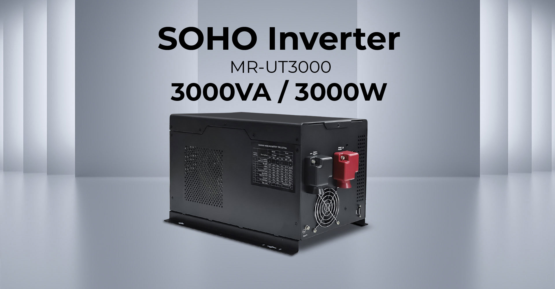
| Rated Output Power (VA) | 2000 | 3000 | |||||
| Rated Output Power (W) | 2000 | 3000 | |||||
| Power Factor | 0 – 1.0 | ||||||
| Nominal Output Voltage (V) | 230VAC | ||||||
| Nominal Output Frequency (Hz) | 50Hz ± 0.3Hz | ||||||
| Auto tracking Main Frequency (Hz) | Yes (Following main first connection) 50Hz@45-54Hz / 60Hz@55-64Hz | ||||||
| Output Voltage Regulation | ±10%rms | ||||||
| Nominal Efficiency | >80% | ||||||
| Over Load Protection (SMPS load) | (100%<load<120%)± 10% : Fault (Shutdown output) after 2 minutes; (120%<load<140%)±10% : Fault (Shutdown output) after 1 minutes, Load>140%±10% : Fault (Shutdown output) after 20s |
||||||
| Surge rating (10s) | 6000VA | 9000VA | |||||
| Capable of starting electric motor | 1 HP | 2HP | |||||
| Output Short Circuit Protection | Current limit (Fault after 10s) | ||||||
| Nominal DC lnput Voltage | 24V | ||||||
| Min DC Start Voltage | 20V | ||||||
| Low Battery Alarm | 21.0VDC ± 0.6VDC for 24V battery | ||||||
| Low DC lnput Shut-down | 20.0VDC ± 0.6VDC for 24V battery | ||||||
| High DC lnput Alarm & Fault | 32VDC ± 0.6VDC for 24V battery | ||||||
| High DC lnput Recovery | 31.0VDC ± 0.6VDC for 24V battery | ||||||
| Power saver | Load≤25W (Enabled on“P/S auto”setting of Remote control) | ||||||
CHARGE MODE SPECIFICATION
| Model | HV MODEL | ||||||
| MR-UT2000 | MR-UT3000 | ||||||
| Nominal Input Voltage | 230VAC | ||||||
| Input Voltage Range | UPS mode: 180 – 265VAC ± 4% INV mode: 160 – 265VAC ± 4% |
||||||
| Output Voltage Range | UPS mode: 180 – 265VAC ± 4% INV mode: 160 – 265VAC ± 4% |
||||||
| Nominal Charge Current | 45A (Max.) | ||||||
| Charge Current Regulation | ±5ADC | ||||||
| Charger Short Circuit Protection | Circuit Breaker | ||||||
| Over Charge Protection | Bat.V≥ 31.4VDC, beeps 0.5s every 1s & fault after 60s | ||||||
| Charge Algorithm | Three stage: Boost CC (Constant current stage) —— Boost CV (Constant voltage stage) —— Float (Constant voltage stage) | ||||||
| Charge Stage Transition Definitions | Boost CC Stage: If A/C input is applied, the charger will run at full currentin CC mode until the charger reaches the boost voltage. | ||||||
| Boost CV Stage: In this stage,the charger will keep the boost voltage in Boost CV mode.The charging current will reduce, until less than 2A, then drop the voltage down to the float voltage. | |||||||
| Float Stage: In float mode,the voltage will stay at the float voltage. If the A/C is reconnected or the battery voltage drops below 12VDC / 24VDC / 48VDC, the charger wil reset the cycle above. | |||||||
Specifications are subject to change without notice, and all product drawings are for reference only.